
What can happen if the load is distributed incorrectly?
- Would you do the same?
- Is there anything to consider?
- Everything is fine. The load hangs on the vacuum lifter.
- Looks great. Do you have any concerns?
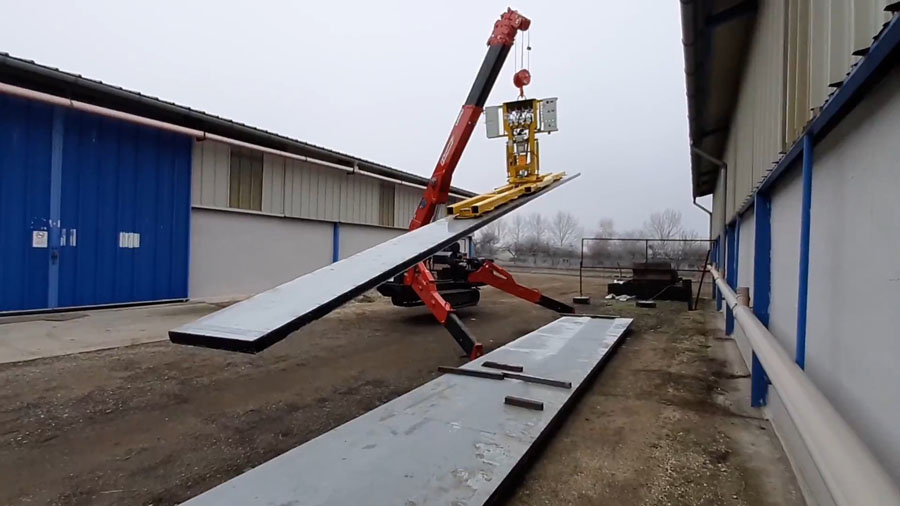
The vacuum lifter should not be used in this way.
Perhaps we should think about it again!
Even if everything worked without any problems, you should think about this application. How is the load distributed across the vacuum cups?
Each vacuum cup has a certain load capacity. If the vacuum cup is overloaded, it will detach from the transported goods. You should take this point into consideration.
It is not so easy to calculate how the loads are actually distributed. We will therefore now take a simplified look at this.
Simple consideration of load distribution
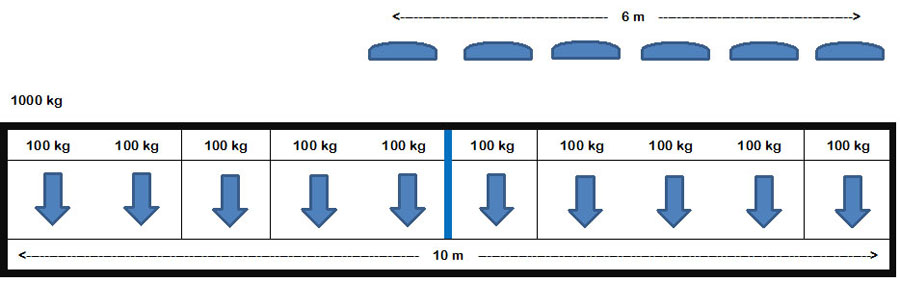
Let's assume that this strip has an even weight distribution over the entire surface. If the strip has a length of 10 metres and a weight of 1000 kg, the load could be divided into 1 metre wide pieces. Each piece would then be assumed to weigh 100 kg, which would be applied to the centre of the metre piece.
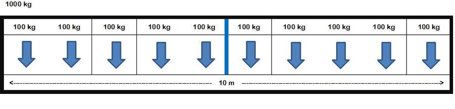
A vacuum lifter with an external suction cup distance of 6 m is used to lift the load horizontally.
If the vacuum lifter is now sucked in at the centre, a symmetrical load distribution can be assumed. However, the outer suction cups are always subjected to a higher load than the inner suction cups.
In this simplified view, the 100 kg plus another 100 kg with a lever arm of 1 m plus another 100 kg with a lever arm of 2 m act on the outer suction cup. This quickly shows that attention should be paid to the correct load distribution.
Anyone can easily see the effect of such a lever arm with a sledgehammer weighing 5 kg. Hold the hammer handle directly behind the weight and stretch out your arm. This is generally quite easy. Now grasp the end of the hammer handle and try to bring the hammer into a horizontal line with your arm outstretched. Did you notice the difference?
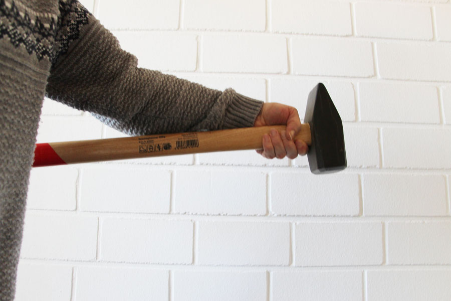
„Short hammer on an outstretched arm“
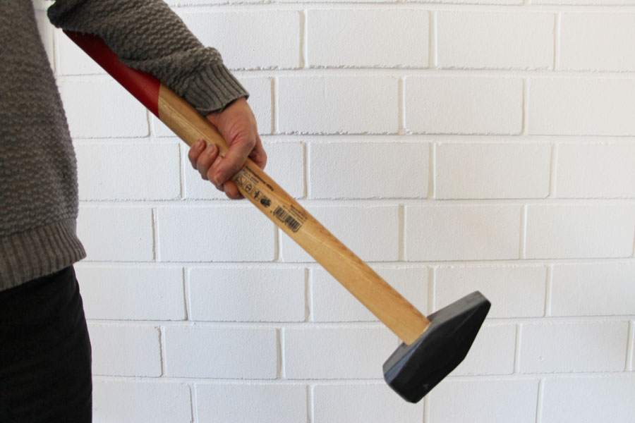
„Try to lift the hammer by holding the hammer handle in the centre with an outstretched arm“
This quickly and simply illustrates the effect of the lever arm.
This symmetrical example alone clearly shows how vacuum cups can be overloaded, even if not even the nominal weight is lifted.
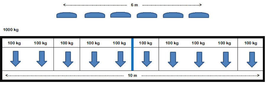
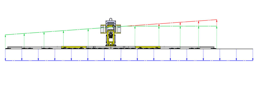
Let us now look at the situation with asymmetrical distribution, when the vacuum lifting device is sucked in on one side.
In the simplified view, considerably more forces now act on the outer suction cup than with the symmetrical load. In addition to the 100 kg, a further 100 kg with a lever arm of 1 m, 100 kg with a lever arm of 2 m, 100 kg with a lever arm of 3 m and a further 100 kg with a lever arm of 4 m are added. Even without considering the lever arm, this is 400 kg more than the other suction cups in our simple analysis.
Here again, a slightly different illustration of the application shown. The blue arrows pointing downwards represent the weight load. The arrows pointing upwards represent the load capacity acting on the suction cups. As vacuum lifting devices should always be designed with a 2-fold safety factor, this is not noticeable in most applications. Especially with multi-circuit vacuum lifting devices. However, the calculated safety is totally sacrificed and in the event of a fault, there is no longer a backup system available. If there is too much, there is already a risk of overload in normal cases.
Our advice
Always try to achieve a symmetrical load on the suction cups.
If this is not possible, consider what forces can act on the suction cup and include the individual load-bearing capacity of a vacuum suction cup in your considerations. If a suction cup is first overloaded and tears away from the load, a chain reaction can quickly occur and the load detaches from the vacuum lifting device.
It is better to think about it beforehand than to look for an explanation for the accident afterwards.
It's about your safety and that of your fellow human beings.